Supported sensors and channels
Who can do this: every role can see channel values on the dashboard and service pages. Only organization administrators register devices, map channels to services, set calibration and change the uplink interval.
This page lists the sensor types Pulse decodes, the channels each one reports, and how readings, uplink intervals and battery levels behave. Physical measuring ranges, probe accuracy and factory reporting periods are not covered here: refer to the manufacturer's datasheet for your model.
How Pulse identifies a sensor type
When an organization administrator registers a device (Admin → Devices → Register a device), the Device profile / sensor type list shows each profile as NAME (OTAA) or NAME (ABP), and only profiles matching the chosen Activation are shown. The profile tells Pulse which hardware the device is and how to decode its messages. All supported types below use OTAA activation. See Devices.
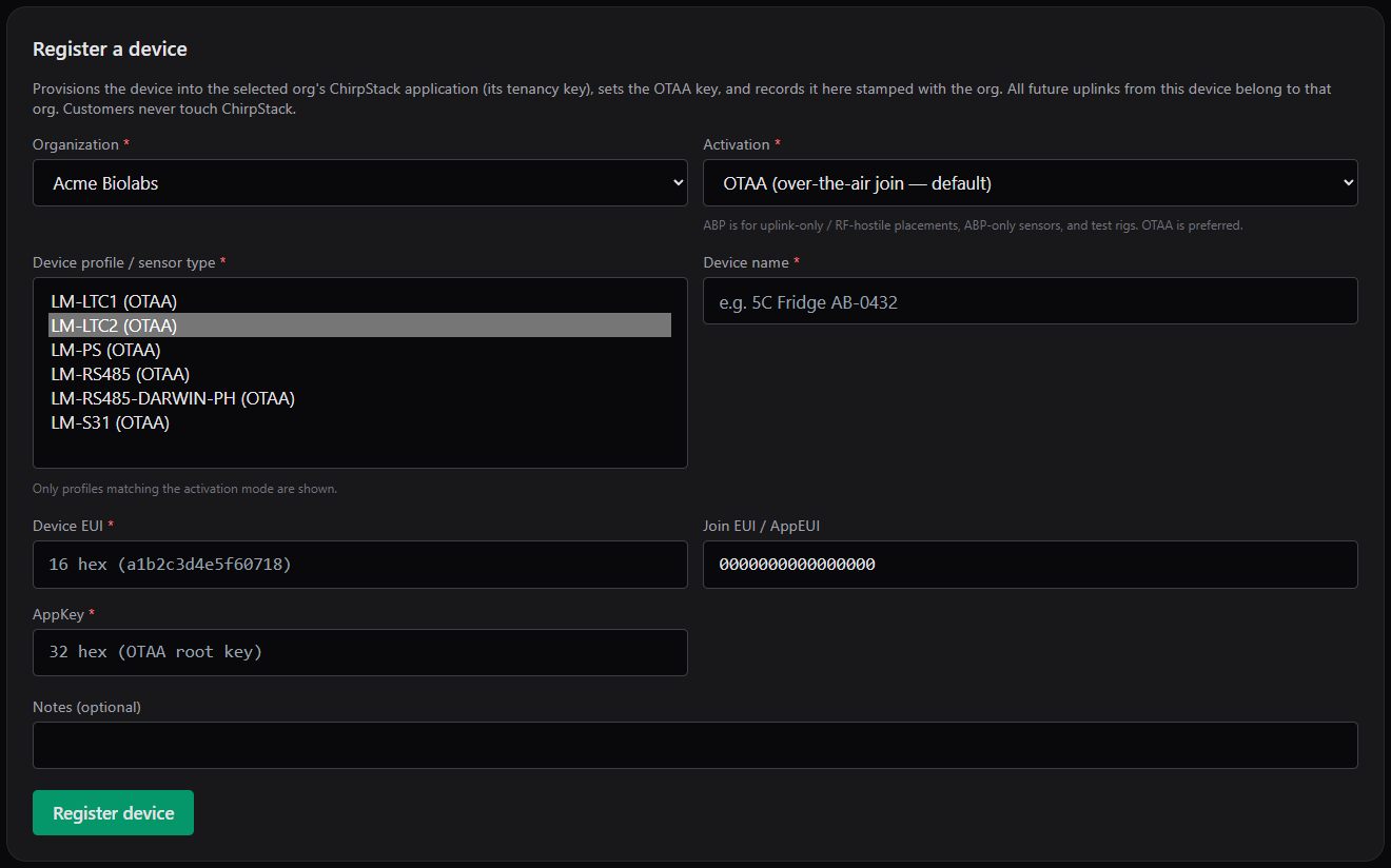
The Register a device form with the Device profile / sensor type list open.
| Profile name (as shown in the list) | Hardware | Measures |
|---|---|---|
LM-LTC1 |
Dragino LTC1-LB temperature transmitter with one RTD probe | Temperature |
LM-LTC2 |
Dragino LTC2-LB temperature transmitter with two RTD probes | Temperature at two probes |
LM-S31 |
Dragino S31-LB | Air temperature and relative humidity |
LM-RS485-DARWIN-PH |
Darwin Chambers PH011-DA stability chamber, read through a Dragino RS485-LB bridge | Chamber temperature and humidity, each with the controller's setpoint |
LM-PS |
Dragino PS-LB analog input (4–20 mA and 0–10 V) | Raw current and voltage from a pressure or level transducer; calibration required |
Choose exactly the profile for your hardware
The list may contain profiles other than those above. A device registered with a profile Pulse cannot decode joins the network and sends messages, but no readings ever appear and no channels become available for mapping. The profile cannot be changed after registration. Contact Lab Monitors support to change a device's profile or to add a new sensor type.
LM-RS485
The list also shows LM-RS485, the generic base profile for the Dragino RS485-LB bridge. A device on this profile reports battery only. Wired equipment on an RS485-LB needs its own equipment-specific profile, such as LM-RS485-DARWIN-PH. Contact Lab Monitors support to add a profile for new RS485 equipment.
Reading the channel tables
- Channel is the name exactly as it appears in the channel list when you add a mapping on Admin → Services, and in the
channelcolumn of CSV exports. The list (headed-- select unassigned channel --) offers only channels that are not yet mapped to any service; remove an existing mapping to free a channel. - Default label is what the dashboard and service page show when the mapping's label is left blank. You can enter your own label and unit on the mapping. The label and unit are also used in alarm notifications: a mapping labelled
Humiditywith unit%producesCRITICAL HUMIDITY ALERTandCurrent Reading: 75 %. See Services and channel mapping and Notifications you receive. - Kind: Measurement is a value you monitor; Setpoint is the target the equipment's own controller is holding; Diagnostic is device health.
- Alarm target says whether it makes sense to put limits on the channel. See Alarm limits and policies.
Every type also reports battery voltage. Battery is not offered as a mappable channel; see Battery and signal.
LM-LTC1
| Channel | Default label | Meaning | Unit | Kind | Reported | Alarm target |
|---|---|---|---|---|---|---|
temp_1 |
Temperature | Temperature at the RTD probe | °C | Measurement | Every uplink, unless the probe is disconnected or faulted | Yes |
LM-LTC2
| Channel | Default label | Meaning | Unit | Kind | Reported | Alarm target |
|---|---|---|---|---|---|---|
temp_1 |
Temperature | Temperature at probe 1 | °C | Measurement | Every uplink, unless the probe is disconnected or faulted | Yes |
temp_2 |
Temperature 2 | Temperature at probe 2 | °C | Measurement | Only when a second probe is connected and reading | Yes, if a second probe is wired |
temp_2 is a conditional channel. It is offered for mapping only after the device has sent at least one valid probe-2 reading; a single-probe LTC2 never creates a temp_2 channel. If probe 2 is disconnected later, temp_2 stops updating while temp_1 continues (see Reading validity).
LM-S31
| Channel | Default label | Meaning | Unit | Kind | Reported | Alarm target |
|---|---|---|---|---|---|---|
temperature |
Temperature | Air temperature | °C | Measurement | Normal periodic reports only; dropped if outside −45 to 130 °C | Yes |
humidity |
Humidity | Relative humidity | % | Measurement | Normal periodic reports only; dropped if outside 0 to 100 % | Yes |
The first message after the sensor is powered on may not be a normal periodic report. Pulse stores only the battery from such messages, so the first temperature and humidity values arrive with the next uplink. The S31-LB's door and interrupt flags are not reported.
LM-RS485-DARWIN-PH
| Channel | Default label | Meaning | Unit | Kind | Reported | Alarm target |
|---|---|---|---|---|---|---|
temperature |
Temperature | Chamber temperature (process value from the temperature controller) | °C | Measurement | When the temperature controller answers | Yes: fixed limits, or percentage deviation from temperature_setpoint |
temperature_setpoint |
(none: the channel name is shown) | Temperature the controller is set to hold | °C | Setpoint | When the temperature controller answers | No: use it as the setpoint channel of a percentage policy |
humidity |
Humidity | Chamber relative humidity (process value from the humidity controller) | % | Measurement | When the humidity controller answers | Yes: fixed limits, or percentage deviation from humidity_setpoint |
humidity_setpoint |
(none: the channel name is shown) | Humidity the controller is set to hold | % | Setpoint | When the humidity controller answers | No: use it as the setpoint channel of a percentage policy |
- If one of the chamber's two controllers does not answer, that controller's two channels are dropped for that uplink; the battery and the other controller's channels are still stored.
- This chamber has no state channel, so a percentage policy on it uses the setpoint channel only.
- For a percentage policy the setpoint must be fresh (received within the service's Stale after (minutes); this check does not use the uplink interval) and non-zero; otherwise the measurement channel shows STALE even though it is still reporting. See Alarm limits and policies.
- If you map a setpoint channel to a service it is shown on the card, in the charts and in CSV exports like any other channel. Contact Lab Monitors support to hide setpoint channels from cards and charts while keeping them available for percentage policies.
LM-PS
| Channel | Default label | Meaning | Unit | Kind | Reported | Alarm target |
|---|---|---|---|---|---|---|
current_mA |
Current | Raw 4–20 mA loop current from the transducer | mA | Measurement (raw) | Every uplink; reads 0.0 when nothing is wired | Yes, after calibration |
voltage_V |
Voltage | Raw 0–10 V input | V | Measurement (raw) | Every uplink; reads 0.0 when nothing is wired | Yes, after calibration |
The PS-LB reports the raw electrical signal, not a pressure or level. The physical value is a straight line through the loop current (4 mA at zero, 20 mA at the transducer's full scale), so convert it with the channel's Scale and Offset on the device's Calibration panel. Calibration applies to new readings only, and the unit shown stays mA unless you change the unit on the mapping. See Calibration. The transducer's probe mode, range code and digital input are not reported.
Reading validity
Pulse only stores readings it can decode. The table shows what causes a reading to be dropped.
| What happened | What Pulse stores |
|---|---|
| The device was registered with a profile Pulse cannot decode | Nothing, ever |
| A message was too short or garbled to decode | Nothing from that uplink |
| One channel in the message was invalid: an LTC probe disconnected or faulted, a Darwin controller that did not answer, an S31 value outside its physical range or a non-periodic S31 report | That channel is skipped; the other channels from the same uplink (including battery) are stored |
| The device's own clock was not set | The reading is stored normally |
Readings are stamped with the time Pulse received the uplink, not the sensor's clock. Times are stored in UTC and shown in the timezone set in your profile.
What you see when a reading is dropped: nothing new. The channel's last good value stays on the dashboard card and service page, and the card's Last: time and the service page's Last telemetry: time do not advance for that channel. Once the gap exceeds the service's stale threshold (twice the device's uplink interval when one has been sent from Pulse, otherwise Stale after (minutes), default 15), the service shows a grey STALE badge with ⚠ No data (stale since …) on its card, appears as a STALE row under Active Alarms, and, if Enable system notifications is on for the service, a STALE notification is sent. The next valid reading clears the stale state. See How alarms work.
Services with more than one channel
The card badge reflects the service as a whole. A single channel that has stopped reporting (for example a disconnected probe 2 on an LTC2) may not turn the whole card STALE while the other channel keeps reporting. Check each channel's Latest line on the service page.
Uplink interval
Who can do this: organization administrators.
Every supported type accepts the Set uplink interval command, in whole minutes from 2 to 120.
- Open Admin → Devices, find the device and click Edit.
- Under Downlinks, enter the interval in minutes next to Set uplink interval and click Send.
- Confirm the prompt
Send 'Set uplink interval' downlink to this device? This commands the hardware on its next downlink window.
Pulse replies Queued 'Set uplink interval' (payload …, fPort 2, unconfirmed). Applies on the device's next downlink window. and records the value as Last interval on the device. Values outside 2–120, or that are not whole numbers, are refused.

The Downlinks section of the Edit Device panel: Set uplink interval and Last interval.
- The command is sent unconfirmed: Last interval shows the value you sent, not confirmation that the device applied it. Check by watching the Last: times on the service page after the next few uplinks.
LM-RS485-DARWIN-PHalso offers Confirmed uplinks (On/Off), which switches the device between confirmed and unconfirmed uplinks.- Pulse does not show a device's factory reporting interval; Last interval reads
—until you send a command. Refer to the manufacturer's datasheet for the factory setting.
Stale detection follows the interval you send
Once you have sent an interval, Pulse marks the device's services stale when no reading has arrived for twice that interval, whatever their Stale after (minutes) says (0 still turns stale detection off). A device left on its factory interval, with Last interval reading —, is judged on Stale after (minutes) alone: set that to at least two to three times the factory interval, or send the interval once so that Pulse knows it. See The stale threshold.
Battery and signal
Every supported type reports its battery voltage in every uplink. Pulse shows it on the service page, in the Latest line under each chart, for example Latest: 4.20 C | RSSI -81.0 | SNR 13.0 | Battery 3.2V (RSSI and SNR are the radio signal strength and signal-to-noise ratio measured by the gateway that received the uplink).
- Battery is reported in volts only; Pulse does not show a percentage or an estimated remaining life.
- Battery is not a mappable channel and does not appear in charts, CSV exports or AI recommendations. It follows whichever channel of the device you have mapped.
- There is no low-battery alarm or notification today. Battery voltage is shown for information. Check it when you review a service, and refer to the manufacturer's datasheet for the voltage at which the battery should be replaced.
- RSSI and SNR are shown for information and cannot be alarmed on.

The Latest line under a chart: value, RSSI, SNR and Battery.